

How to Size a Buffer Tank
How to Size a Buffer Tank — Tanpera engineering guidance covering process requirements, design criteria and recommended equipment.
Key takeaways
- How to Size a Buffer Tank — Tanpera engineering guidance covering process requirements, design criteria and recommended equipment.
- Derive total system water volume (piping, heat exchanger, equipment) from the piping plan
- Determine the lowest active equipment flow and the minimum operating point
- Confirm the chiller/boiler manufacturer's minimum flow-rate requirement
- Calculate buffer volume for the allowable ΔT (typically 0.5–1.5 °C)
Buffer Tank Sizing Steps
Follow this sequence when calculating volume for central heating and cooling circuits:
- Derive total system water volume (piping, heat exchanger, equipment) from the piping plan
- Determine the lowest active equipment flow and the minimum operating point
- Confirm the chiller/boiler manufacturer's minimum flow-rate requirement
- Calculate buffer volume for the allowable ΔT (typically 0.5–1.5 °C)
- Assess extra reserve for hydraulic balance at district-energy interfaces
- Check system pressure together with expansion and degasser capacity
Volume Calculation Inputs
Typical sizing steps:
| Process step | Heat-transfer duty | Recommended equipment |
|---|---|---|
| 1. System volume | Combined water in piping, heat exchanger and equipment | Piping plan |
| 2. Flow profile | Min/max instantaneous flow and part-load | Automation data |
| 3. ΔT target | Allowable temperature deviation | Design criterion |
| 4. Tank volume | Buffer capacity = f(flow rate, ΔT, cp) | Buffer tank |
Design Parameters
Minimum engineering inputs for sizing:
- Primary and secondary circuit flow rates and inlet–outlet temperatures (°C)
- System static height and operating pressure
- Glycol ratio and fluid viscosity (cooling circuits)
- Part-load profile and minimum equipment flow
- Expansion, degasser and buffer-tank integration
- Maintenance clearance and plant-room layout constraints
Tanpera Approach
End-to-end support matched to project and operating needs:
- Project-based thermal and hydraulic sizing
- Site installation, commissioning and performance testing
- Process integration backed by sector reference experience
- After-sales spare plates, gaskets and service network
Recommended Tanpera Products
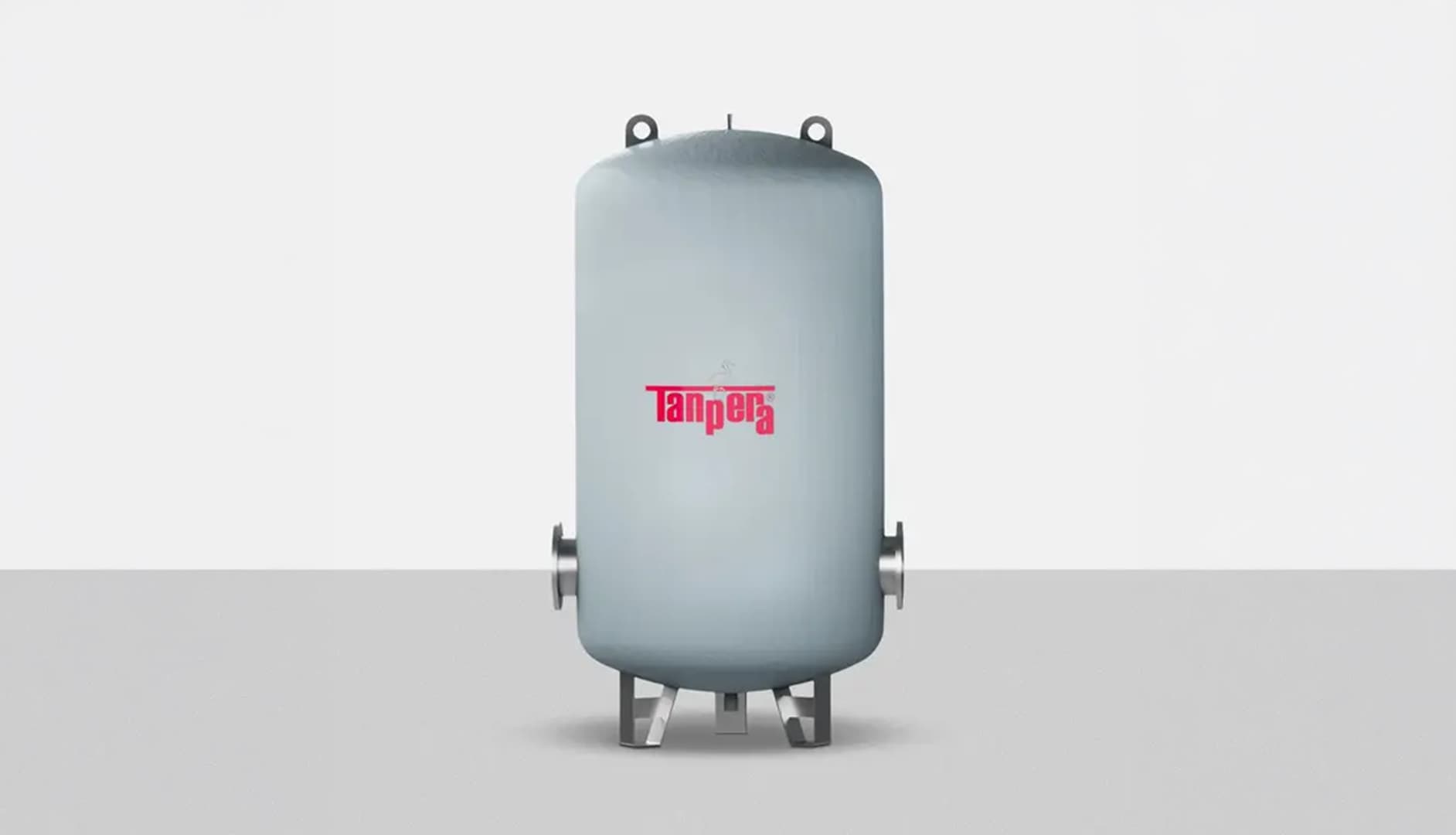
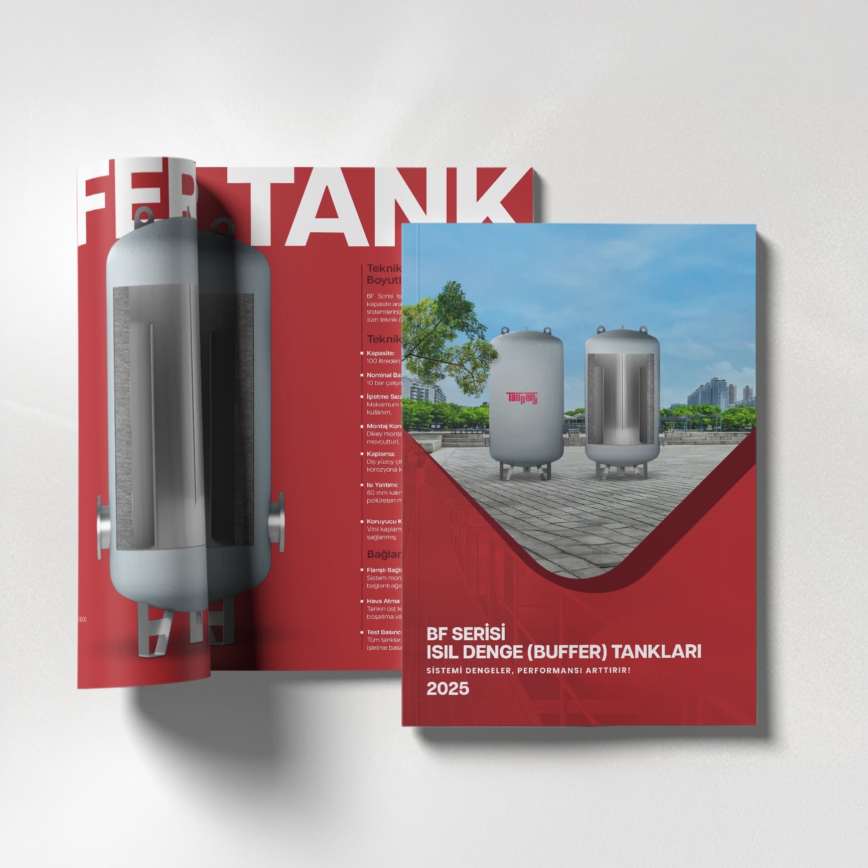
Buffer (Thermal Balance) Tank
Hydraulic balance and load buffering. Capacity reserve for central heating and cooling circuits.
Equipment Selection Notes
Recommended equipment groups for this application:
- Buffer-tank volume must not be selected below the chiller/boiler minimum flow requirement
- Tank location and connection orientation should be planned to prevent short-circuit flow
- Insulation and corrosion protection are especially critical on cooling circuits
- Tanpera buffer tanks are supplied with flange and connection configurations matched to project volume
Related Solution Center Articles
Explore the detailed brochure
Find Tanpera product groups, technical advantages and application recommendations in the brochure.
- Product groups
- Technical advantages
- Application recommendations
References & standards
- ASHRAE — Hydronic system design fundamentals — Buffer tank and minimum flow sizing
Frequently Asked Questions
How is buffer tank volume calculated?
A practical approach is V ≈ Q × t / (ρ × cp × ΔT), where Q is the minimum flow-rate difference, t is the buffer duration in minutes, and ΔT is the allowable temperature deviation. On Tanpera projects, automation data and equipment curves are evaluated together.
Is a buffer tank mandatory on a chiller circuit?
On multi-chiller plants with a variable load profile, a buffer tank or hydraulic separator is often required to protect the minimum flow rate. A single chiller under steady load may need only a smaller volume.
What is the difference between a buffer tank and a hydraulic separator?
A buffer tank provides volume buffering; a hydraulic separator decouples primary and secondary circuits by pressure. On large campus projects, both may be used together.
What is the role of a buffer tank in data-center cooling?
It limits temperature swing during sudden IT load changes and stabilizes flow on CRAC/CRAH circuits. Tanpera data-center references typically combine a buffer tank, plate heat exchanger and pumped expansion system (PGS).